Circuit
Figure 1 Ornithopter circuit.
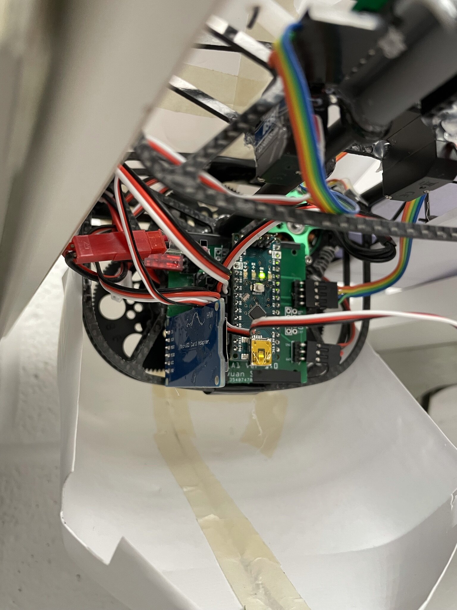
The circuit is quite crowded (Figure 1). To make wiring easier, I designed and ordered two-layer PCBs (Figure 2).
Figure 2. My designed PCB. 5$ for 10 pieces. Incredibly affordable.
The final wiring is a little bit untidy but is still acceptable (Figure 3).
Figure 3. Circuit on the fuselage. Fabricated in May. Photoed on July 13 2021.
This is the first time I do electronics, and it literally took me 3 weeks to do and redo all those wirings, study protocols, and do the coding.
Appendix: List of Components
Microcontroller
9DoF IMU with Fusion
Hall Latch
Data Recorder
Buzzer
Arm Servo
Tail Servo
BLDC
ESC with BEC
Arduino Nano V3.0
Adafruit BNO055
US1881EUA
HiLetgo SD Card Module
No Name (from Amazon)
TGY-EX5252MG
TGY-D56LV
Cobra C-2204/58
TAROT TL300G1


